Introduction to the issue
The subject of data recovery has become shrouded in myths and legends. Popular culture often presents a highly simplified picture of the work carried out by police officers and other agencies. In the world of fiction, they have at their disposal a variety of magical briefcases and boxes that allow them to recover data, bypass security measures and gain access to information stored on various media quickly and easily.
Belief in this fictional world is also fuelled by ill-advised statements from non-technical officials, prosecutors, commanders or press officers. Without citing specific examples, as this is not about criticising specific statements by specific individuals, those who speak out and take a stance on behalf of the service should be aware that words spoken publicly to boost one’s own morale and confidence may give rise to unrealistic expectations regarding the work of other officers, particularly forensic technicians. A realistic assessment of data recovery capabilities is also not facilitated by regulations governing data destruction procedures, which are detached from technical knowledge and are not always applied reliably by data destruction companies to suggest mysterious capabilities of various agencies’ laboratories that are not grounded in the laws of physics or technical knowledge.
In reality, officers often face numerous difficulties when carrying out their duties. They possess neither the magic boxes familiar from crime dramas nor fantastical superpowers. Furthermore, certain tasks are often not carried out by internal forensic laboratories, but authorities commission commercial firms to perform them, including those offering similar services on the open market. The reasons for this state of affairs are complex and involve many factors, ranging from available equipment and the ability to purchase necessary parts to the training system for officers, in which it is often the case that the most important thing is that the number of certificates submitted to HR matches the requirements.
In practice, whether data can be recovered or not is determined by the laws of physics. Digital information is an interpretation of certain physical states representing logical ones and zeros. The details of the physical representation of logical states and the encoding and decoding processes vary depending on the type of storage medium; however, as long as the relevant physical states still exist, the data is recoverable, and if they are destroyed or altered, data recovery becomes impossible.
Unfortunately, we do not live in an ideal world, and not in every case where data recovery is theoretically possible will it actually be recovered in practice. Often, budgetary, time or technological constraints stand in the way of a successful outcome. The availability of donors proves to be a significant problem, especially in the case of niche, less popular drive models.
It also happens that data recovery ends in failure, or even the irretrievable loss of data as a result of human error. That said, data recovery encompasses a very wide range of tasks, from those so simple that even a layperson using the most basic software can manage them, to those so complex that they would qualify as major research projects, were the necessary resources made available. Therefore, in certain situations, even the best specialists are helpless, although the data is recoverable from a physical point of view. On the other hand, one all too often encounters critical errors resulting from incompetence, hasty actions not justified by diagnostics (in extreme cases, even bypassing diagnostics altogether), carelessness, and disregard for basic best practices and principles of data storage security.
The following sections of this publication will outline the basic principles of how data storage media operate and the causes of data loss. For each category of fault, the available methods of action will be described, along with the practical and physical limits of data recovery. Directions for the development of data recovery techniques will also be indicated, which in the future may lead to a reduction in the ‘grey area’ between practical and physical limitations. The description of each fault category covers the most typical symptoms, allowing the damage to be classified into the correct category with a high degree of certainty. Finally, the most important guidelines and best practices will be outlined to help minimise the risk of further deterioration of the media being secured and the loss of data recovery potential.
Fundamentals of data storage devices
Digital data storage media differ significantly from one another in terms of their structure, design, operating principles and the physics of information storage. These differences affect their susceptibility to failure, as well as the methods and possibilities for data recovery. Nevertheless, it is possible to present a general model of how data storage media function, analogous to the ISO/OSI RM model describing the structure of communication in a computer network. In a sense, data storage media can also be viewed as devices used to transmit information, not over distance, but over time.
| Logical interpretation | Programmes supporting various file formats |
| Logical addressing | MBR, GPT, file systems, RAID |
| Communication protocols | ATA, SCSI, SD/eMMC, NVMe, USB |
| Physical addressing | LBA<->PBA, FTL, TRIM |
| Encoding/decoding | MFM, RLL, XOR, ECC |
| Logical states | ‘0’ and ‘1’ – interpretation depends on the convention adopted |
| Physical states | Magnetisation, electrical charge, light reflection, resistance |
Logical interpretation
From the user’s perspective, data is stored in the form of files – organised units containing a specific type of information saved in a specific format. These may include text documents, spreadsheets, images, databases, audiovisual recordings and others. Each file type has a specific internal structure that allows its contents to be displayed in a user-friendly manner using appropriate software.
The contents of some file types can be read, at least in part, directly in a hexadecimal editor without the use of dedicated software. This applies, for example, to text files or fragments of unencrypted databases. Analysing the contents of other files without the use of appropriate tools is practically impossible. Encrypted files, password-protected files and audiovisual materials recorded using non-standard encoding methods can be particularly problematic.
Logical addressing
Files are usually organised within a directory structure located on a partition. File systems are responsible for managing the logical structure of the partition. Each partition can be formatted using a single file system of the user’s choice; furthermore, if there are several partitions on the storage medium, each can be formatted using a different file system, regardless of the file systems on the other partitions.
Partitioning (with a few exceptions) is described in partition tables in the Master Boot Record (MBR) or in GPT (GUID Partition Table) tables. Typically, a partition is located entirely on a single storage medium, but there are also solutions where it spans several discs. The most popular of these solutions are RAID (Redundant Array of Independent Discs) arrays, which allow multiple discs to be combined into a single logical unit. We encounter a kind of virtual partition in the case of virtual machine files containing internal virtual file systems. Indeed, binary images created during the preservation of digital evidence can also be viewed in a similar light.
The internal logical structures of file systems differ from one another, although many similarities and common architectural principles can be observed across numerous file systems. Differences between file systems and the preferences of operating system developers mean that operating systems are only capable of supporting a select subset of file systems. Data stored in a file system not supported by the operating system will not be visible under that system, as the operating system will be unable to handle addressing within the logical structure of that file system.
In this case, there is no actual data loss – access to the data can easily be obtained by identifying the file system on the partition and mounting it in an operating system that supports that file system. A certain problem may be posed by niche file systems specific to particular devices and manufacturers, and supported only by software specific to those devices and manufacturers. Such file systems can be found, for example, in the automotive industry, industrial systems, Internet of Things devices and drones, and it is to be expected that, as technology advances, they will also appear in other devices, and their importance will grow.
This is a significant issue, given that electronic devices, various sensors and other components of larger systems, devices and vehicles may collect data that is important from the perspective of computer forensics. This data may constitute all the more significant digital evidence because its modification, the potential for manipulation, and sometimes even the very awareness of its recording generally requires users to possess significantly greater technical competence than similar activities involving data stored on computers or smartphones. One of the reasons for these difficulties is the lack of available documentation, which simultaneously hinders the analysis of the evidence being secured.
Communication protocols
In order to read files from a disc, you need to communicate with it properly. In the early days of computer technology, closed architectures using manufacturers’ proprietary communication protocols predominated. However, as computerisation progressed, there arose a need to ensure compatibility between components from different manufacturers. This need led to the standardisation of communication protocols.
The first standards describing the operation of hard drives were the SCSI (Small Computer System Interface) and ATA (Advanced Technology Attachment) standards, developed in the first half of the 1980s. Over the years, these standards have evolved (e.g. they have given rise to serial bus implementations – Serial Attached SCSI and SATA) and to date, almost all hard drives, most SSDs (Solid State Drives) and Compact Flash memory cards are compatible with them. Furthermore, the SCSI standard has given rise to a number of other communication protocols, including USB (Universal Serial Bus) and NVMe (Non-Volatile Memory Express).
Since data storage devices are block devices (unlike character devices, they do not allow for the addressing of individual bytes – ‘characters’ – but address data in larger blocks – hence their name), communication protocols also describe the addressing and transfer of data in blocks. At the time when the SCSI and ATA standards were being developed, hard drives and virtually all other data storage devices available at the time addressed data in 512-byte physical sectors; consequently, the data addressing unit adopted by these standards was the 512-byte LBA (Logical Block Addressing) sector. The introduction of LBA addressing, which involves assigning consecutive numbers to physical sectors starting from 0 until the storage medium’s capacity is exhausted, was a significant breakthrough.
Previously, data was addressed by referring directly to the physical sector addresses in CHS (Cylinder – Head – Sector) addressing, which required differences in the physical addressing of discs to be accounted for in the logical addressing at the file system level; vestiges of this can still be found in the logical structures of many file systems. The introduction of LBA addressing freed file systems from the need to concern themselves with physical addressing, whilst forcing disc manufacturers to implement solutions responsible for converting LBA addresses into physical addresses. On the other hand, manufacturers gained flexibility and new possibilities for optimising disc space utilisation and managing defects, which in a short time contributed to a significant increase in the recording density and capacity of available hard discs.
Furthermore, the standardisation of communication protocols and the invention of LBA addressing paved the way for combining drives into RAID arrays. Building such arrays across multiple drives by directly referencing the physical addressing of each would be extremely complex. LBA addressing allows the user to view the drives as a single logical entity addressed by a continuous sequence of LBA sector addresses, which is converted by the array controller into the LBA addresses of the individual drives.
The introduction of LBA addressing also facilitated the use of semiconductor storage media, such as memory cards, USB sticks and SSDs. Semiconductor storage media do not have platters, tracks or sectors, and the internal addressing of the media in Flash-NAND integrated circuits is completely different from that of hard drives. Although file systems designed specifically for semiconductor storage media and taking their physical addressing into account, such as YAFFS and JFFS, have been developed, however, due to the great diversity and rapid pace of change in Flash-NAND chips, as well as the limited number of operating systems supporting these file systems, they have not gained widespread popularity and are found only in niche applications.
LBA addressing, which is independent of physical addressing, ensures full compatibility between file systems and different types of storage media. The conversion by firmware of internal addressing units of various sizes into 512-byte LBA sectors ensures that this addressing scheme is highly resistant to technological advances, making it versatile and long-lasting. This is why it is used by all commonly used communication protocols for handling data storage media.
Physical addressing
Physical addressing in data storage media refers directly to physical allocation units and is not accessible to the user. Even if diagnostic software, designed for data recovery or forensic analysis uses the concept of physical addresses or sectors, this term usually refers to LBA addresses. Actual physical addresses refer to the physical coordinates of sectors in a rotational reference system on hard disc platters, or blocks and pages in NAND Flash chips on semiconductor storage devices.
Since the exchange of data, commands and messages between data storage devices and other devices takes place using LBA addressing, it is necessary to convert LBA addresses to physical addresses. This is handled by a part of the storage device’s firmware known as the translator. Due to significant differences in the design and physics of information storage between hard discs and semiconductor storage devices, the solutions used in their logical-to-physical address translation subsystems also differ.
Furthermore, as technology advances, the firmware evolves, including the translation subsystem. This results in subtle differences between individual families of storage media, even within the same firmware architecture. Therefore, the issue of translating logical addresses to physical addresses is one of the most complex topics in data recovery.
The translation subsystem was relatively simple in older generations of hard drives, where it essentially involved assigning sequential LBA numbers to physical sectors based on a specific algorithm. The algorithms for creating the translator became more complex as progress was made in optimising space utilisation, implementing zones with varying numbers of sectors per track, and developing defect management methods. The relatively fixed assignment of LBA addresses and the simplicity of the translation subsystem contributed to its high reliability until the advent of Shingled Magnetic Recording (SMR) drives.
Shingled magnetic recording allows for increased recording density through partial overwriting, thereby narrowing the previous track when writing the next one. A consequence of this recording method is the loss of the ability to rewrite individual sectors – since the recording head induces a magnetic field wider than the track width, such a write operation would damage the contents of sectors on adjacent tracks. Therefore, when there is a need to change the contents of a sector, it is necessary to rewrite the entire group of tracks. Such rewriting of entire groups of tracks negatively affects the drive’s write performance.
To avoid this effect, manufacturers employ various methods to optimise writing. Generally, these boil down to writing the new contents of LBA sectors not where those sectors were originally physically located, but where it is most convenient in a given situation. This breaks the fixed mapping of logical addresses to physical sectors and necessitates an increase in the complexity of the logical-to-physical address translation subsystem, so that it can track the current location of LBA addresses within physical sectors in real time.
The situation is different in semiconductor storage media, where the inability to directly overwrite existing content from the start has necessitated the rotation of LBA addresses across physical addresses. The content of Flash-type chips cannot be altered by simple reprogramming, but requires the content to be erased first and then reprogrammed. Therefore, NAND Flash memory is divided into two types of physical allocation units: pages, as units for programming and reading, and blocks containing multiple pages, as units for erasure.
Storage media using this type of memory always maintain a certain number of free, erased blocks so that these can be programmed with new content. And when they are programmed, appropriate LBA addresses are assigned to them in the Flash Translation Layer (FTL) tables. At the same time, blocks containing obsolete data are evicted from the LBA address space, allowing them to be erased and prepared to receive new information.
This is a highly simplified model of managing the translation of logical addresses to physical addresses in semiconductor media. Since programming and erasure operations wear out NAND Flash circuits, leading to their failure, and the price of increasing storage density is a reduction in the lifespan of this type of memory, manufacturers are forced to develop methods for managing defects and for limiting and balancing wear. One of the most important optimisation methods is the TRIM function, which allows the physically stored information to be limited solely to areas allocated within the logical structures of file systems.
The TRIM function not only helps to reduce wear on NAND flash memory caused by programming and erasure operations, but also improves the performance of these operations. For this reason, it has also been adopted for use in SMR drives, which suffer from write performance issues. However, the TRIM function has a significant drawback from the perspective of data recovery and digital forensics. Data deleted at the level of the file system’s logical structures almost immediately ceases to be accessible via LBA addressing, and the only chance of recovering it is to search for it via physical addressing.
Due to the increasing complexity and dynamics of the changes occurring within the translation subsystem, it is prone to errors and damage. Translator issues are the main cause of semiconductor storage failures and are particularly significant in the case of SMR drives. As each data storage unit has certain individual characteristics, such as the number and location of defects, each translator is unique and cannot be replaced by another copied from a different storage unit.
Data encoding and decoding
Data stored on storage media has been transformed through the encoding process and differs significantly from what the user sees in their files. There are many reasons why data on digital storage media cannot be stored as a raw stream of zeros and ones, as the user might see it in a hex editor. The most important of these include the need to ensure data consistency and correct possible errors, as well as the aim to pack data onto the medium as efficiently as possible.
Since there is a risk of errors and distortions occurring at every stage of data storage and transmission, various types of checksums (e.g. CRC – Cyclic Redundancy Code) and error correction codes (ECC) are widely used. Solutions of this type are used in both communication protocols and data storage media. And whilst in the case of communication protocols these are described in the relevant standards, in the case of data storage media the details of their implementation depend on the manufacturer and the firmware architecture, and one can often observe certain differences within a single device model running different firmware versions.
In the case of semiconductor storage media, other redundant information is also added to the user data stored in pages. In particular, this concerns logical block number markers, sometimes also logical page numbers, and counters used by wear-levelling algorithms to monitor the wear of individual blocks. The details of this information depend to a large extent on the firmware solutions implemented in a given storage medium. The arrangement of user data and redundant information within a page is referred to as the page format.
Data is also very often randomised. Natural user data frequently contains long sequences of identical symbols or repetitive patterns. Such data, due to wave reflections, the formation of standing waves and parasitic harmonics, is more difficult to transmit without errors, and, due to inductive phenomena, also to store. Therefore, to reduce the risk of bit errors, the data is transformed, usually using the exclusive-OR (XOR) logical function and special, sometimes dynamically generated, patterns.
One of the common data processing techniques is encryption. Encryption is commonly associated with data security and protection against unauthorised access; however, the popularity of hardware encryption in data storage devices has a second justification. Encryption algorithms also randomise data very effectively, and particularly in the case of SSDs, it is reasonable to suspect that this is the main reason for their widespread adoption.
As semiconductor storage media are subject to wear as a result of erasure and programming operations, manufacturers strive to limit the number of such operations performed. One of the techniques they employ is internal data compression. This reduces the volume of stored information, and in the process, the data is also randomised.
In optical and magnetic media, data is additionally encoded to optimise data packing density. The original method of data encoding in hard drives was the FM (Frequency Modulation) method. It involved recording a clock signal and inserting additional pulses between the clock pulses for bits with a value of ‘1’. If there was no ‘1’ between the clock pulses, this represented a logical zero.
This was a very inefficient encoding method, which posed a significant barrier to the development of magnetic media. Therefore, over time, it was replaced by the MFM (Modified Frequency Modulation) method, in which the number of clock pulses was reduced. However, the truly significant potential for increasing storage density in hard drives emerged as a result of the development of CDs (Compact Discs).
Since, in the case of optical media, it is easier to detect a change in the physical state of the medium than to distinguish the reflection of light from burnt and unburnt areas (pits and lands), the EFM (Eight-to-Fourteen Modulation) encoding method was developed for them. This involved encoding the data in such a way that there was always at least one zero between each one. This resulted in a longer bit sequence (each 8-bit byte expanded to 14 bits), but at the same time made it easier to pack these bits onto the physical medium.
In this encoding method, easily detectable pulses represent logical ones, and the number of zeros between these ones is calculated based on the time elapsed between individual ones. This requires precise control of the drive’s rotational speed to ensure a signal of stable frequency is read, but allows more information to be packed onto the medium within the given physical limitations. And, following the example of the EFM method used in CDs, a family of RLL (Run Length Limited) codes was developed for use in hard drives.
RLL encoding made it possible to dispense with the clock component of the recorded signal and achieve a significant increase in recording density. The number of zeros that may occur between two ones depends mainly on the ability to maintain correct signal synchronisation, its decoding, and the correction of bit errors. A more detailed description of data encoding in hard drives can be found in the book Coding and signal processing for magnetic recording systems by Bane Vasić and Erozan M. Kurtas.
Logical and physical states
User data is a logically interpreted sequence of bits – zeros and ones – that is, logical states read from a physical medium. Each logical state is an interpretation of the physical state of the medium. Whether a given physical state is logically interpreted as ‘0’ or ‘1’ depends solely on the convention adopted, just as the convention determines whether a negative charge is assigned to an electron and a positive charge to a proton. If these designations were assigned in reverse, physics would remain unchanged; only its description would change.
The basis for logical interpretation can be various physical states, both stable (non-volatile media) and those requiring a power supply (volatile media). In the case of volatile media, it is not possible to recover data after disconnecting them from the power supply. Such a possibility exists only when the physical states remain stable regardless of the external power supply.
Non-volatile media utilise many physical phenomena that can be interpreted logically. The most important of these include surface magnetisation (magnetic media) and electrical charges stored in the floating gates of transistors (semiconductor media). Optical media utilising surfaces that reflect or scatter light are still in use. In the future, however, we can expect data storage media utilising phenomena related to changes in resistance.
Recording on magnetic media involves organising the magnetisation of the magnetic surface. Reading takes place by moving the medium beneath a read head, in which an electrical signal is induced. The pulses induced in this signal by areas of variable magnetisation - domain walls, are interpreted as logical ones. The absence of such pulses signifies logical zeros. The exact method of signal interpretation depends on the details of the encoding implementation.
In the case of semiconductor media, modified NPN field-effect transistors (FET) with a depletion channel are used, which accumulate electrical charges in floating gates. Since the accumulated electrical charge closes the N-channel, a typically charged floating gate was interpreted as a logical ‘0’, and an empty one as a ‘1’. Following the introduction of multi-state technology, which allows more than 1 bit to be stored in a transistor, the logical interpretation of the charge became more complex. The logical value depends on the voltage applied between the source and drain required to turn the transistor on.
Optical media are pressed or burned discs where sections that reflect light better or worse appear alternately along the track. A sensor records changes in light reflection, and these changes are interpreted as logical ones. The decoder circuit calculates the number of zeros between ones based on the time elapsed between the occurrence of successive ones, as described in the section on data encoding.
In the future, media based on phenomena related to changes in resistance may gain popularity. Typically, in such memories, a logical one corresponds to a low-resistance state, and a zero to a high-resistance state. Among the most promising are phase-change memories (PCM), which have already been tested in real-world devices, as well as magnetoresistive memories (MRAM).
Phase-change memory utilises chalcogenides – substances that can exist in either a crystalline or amorphous (irregular, glass-like) form. If a chalcogenide is heated and then slowly cooled, a low-resistance crystal is obtained. If the chalcogenide is cooled rapidly, it does not have time to crystallise and solidifies in an amorphous form with high resistance.
Concepts for using magnetoresistive phenomena for data storage emerged as early as the 1970s, but were abandoned as having little potential. Everything changed following the discovery of the giant and tunnel magnetoresistance phenomena, which gave new impetus to work on magnetoresistive memories. The essence of the concept boils down to the use of two layers of magnetic material magnetised in the same way (parallel) or in opposite directions (anti-parallel). In the case of parallel polarisation, the resistance is significantly lower than in the case of anti-parallel polarisation, which provides the basis for distinguishing between logical states.
In addition, work is underway on electrochemical memories, in which changes in resistance are driven by the reduction and oxidation of metals. Metals have a significantly lower resistance than their oxides, which allows different logical values to be assigned to them. Another example of resistive memory is carbon nanotubes and structures built from them with varying resistances.
Causes of data loss and options for data recovery
The loss of access to data can be caused by a variety of factors. Different types of storage media vary in their susceptibility to different kinds of damage and in their potential for data recovery. However, just because data recovery fails due to practical obstacles does not necessarily mean that recovery is impossible. The following sections will outline the most significant causes of data loss, methods for diagnosing these issues, and techniques for data recovery.
Electronic faults
Electronic damage is most often caused by connecting a data storage device to an incorrect power supply. The effects of this type of damage are typically limited to components that are not essential for data storage and are generally easy to replace, such as fuses, Zener diodes or resistors. Therefore, in most cases, repairing the device is sufficient to regain access to the data.
Electronic faults can generally be identified quite easily. Devices with this type of damage do not start up, do not respond to power, or exhibit symptoms typical of a short circuit, such as components becoming very hot and high current draw, which often leads to the power being cut off or overload and short-circuit protection mechanisms being triggered. Damaged components (blown fuses and resistors, shorted diodes and capacitors) can be identified using a multimeter.
If the storage device boots with its typical current draw and places a normal load on the bus, even if it is not recognised by the BIOS or operating system, electronic damage can be ruled out with near certainty. In particular, the fact that the motor starts and the platters spin up allows electronic damage to hard drives to be virtually ruled out. In the case of SSDs, it is worth checking the operating temperature of the controller and comparing it with the operating temperature of a working, similar drive using the same controller. Depending on the controller model, its normal operating temperature can range from approx. 30 to over 60 ºC.
In some cases, the damage proves to be more extensive, and in the case of hard drives, it becomes necessary to replace the electronics with a working unit. It is important to remember that the days when it was sufficient to simply swap in an identical printed circuit board (not necessarily from the same model – the same electronics are used across entire model families) ended around 20 years ago. The development of hard drives has also been accompanied by the development of firmware and the growing importance of individually programmable parameters (adaptives). Therefore, it is now necessary to re-solder the donor’s electronics, which contain part of the patient’s EEPROM (Electrically Erasable Programmable Read-Only Memory) firmware.
The EEPROM is usually housed in an SOP-8 (Small Outline Package 8) integrated circuit. In some cases, there may be more than one memory of this type – in which case, of course, all must be re-soldered. In other models, the EEPROM is sometimes integrated within the signal processor. In such situations, it is necessary to re-solder the signal processor or read its contents and program the processor on different electronics. If the signal processor containing the internal EEPROM is damaged, it is still worth attempting to read the EEPROM’s contents. Such attempts are often successful, even in the case of integrated circuits with burnt-out holes.
The loss of EEPROM contents can complicate, and in many cases practically prevent, the recovery of access to the data, even though it still exists on the drive. For some drive models, methods exist to reconstruct the EEPROM contents and recover data; however, for example, for Seagate’s F3 generation – an architecture that has been on the market for over 15 years – no such method exists. Developing such a method is probably possible, but it would require oscilloscope analysis of the signal captured directly from the magnetic head assembly. Access to data can also be rendered practically impossible by the loss of encryption keys, which may be stored in the EEPROM of a USB-SATA adapter for external drives or in the signal processors of certain hard drives (e.g. WD drives from the Spyglass families).
A specific category of failure for SSHDs (Solid State Hybrid Drives) is Flash-NAND buffer failure. SSHDs are hard drives equipped with an additional Flash-NAND buffer, typically with a capacity of 4–8 GB, used to store the contents of the most frequently read sectors, including those in the service area. This is not typically an electronic fault – it most often results from wear on the Flash-NAND chip and the occurrence of errors in its contents.
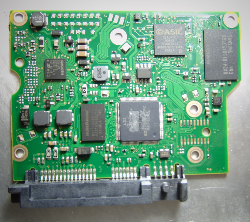
This fault manifests itself as a failure to respond to power supply due to communication problems with the buffer; however, in this case, no electronic components are damaged. In some cases, clearing the contents and initialising the buffer helps, but more often than not, the entire printed circuit board needs to be replaced. As the electronics buffer taken from a donor will contain service information incompatible with the patient, it must be cleared and initialised. As with other situations involving the replacement of electronics, the original EEPROM needs to be re-soldered.
In the practice of computer forensics, intentionally damaged media are encountered more frequently than in typical cases of natural faults. In the case of electronic faults, intentional damage is most easily caused by connecting the device to a power supply delivering a higher voltage or by flooding the device with various liquids. Damage caused by the first of these methods generally differs little from natural faults. If traces of liquid spillage are detected, the first step is to clean off the substance with which the device was flooded, remove any traces of corrosion, and only then proceed with further diagnostics. If there is a suspicion that liquid may have entered the interior of the hard drive’s hermetic enclosure, check its internal condition before powering it on and, if necessary, clean the platters and carry out the necessary repairs to the mechanical subsystem.
Whilst, in the case of hard drives, replacing the PCB (Printed Circuit Board) with a working one is generally a simple, cheap and effective way of repairing electronic faults, in the case of semiconductor storage media and devices with built-in Flash memory (e.g. eMMC – embedded MultiMedia Card or MCP – Multi Chip Package), repair by simply replacing parts is not an option. Therefore, in the case of such devices, the first priority should be to restore them to full working order. If, for some reason (e.g. damage to the laminate, excessive corrosion) this is impossible, the next option for data recovery is to desolder the memory chips, read their contents on a programmer and further analyse the binary images using methods analogous to those for firmware damage, with all their limitations.
And due to these limitations, particularly encryption, reading the contents of memory chips often cannot lead to data recovery in practical situations. Therefore, in certain situations, it is reasonable to re-solder the controller and memory chips onto a different PCB. However, re-soldering the memory chips themselves carries a high risk of destroying their contents as a result of them being initialised by a foreign controller. Similarly, in the case of mobile devices, IoT devices and similar, it is necessary to re-solder their processors or controllers and EEPROMs, partly because these chips may store the encryption keys necessary for decrypting the data.
Mechanical damage
Mechanical damage to data storage media warrants particular attention, as it is easy to cause deliberately and quickly, for example when apprehending a suspect. Due to their design, hard drives are far more susceptible to mechanical faults than solid-state drives. In the case of the latter, the faults encountered are usually relatively simple to identify and rectify, such as broken connectors. Such damaged connectors can be replaced, and in the case of damage to the PCB laminate, the fault can be bypassed by soldering wires behind the damage.
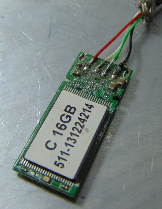
Mechanical damage of semiconductor media
The only way to physically destroy data on semiconductor storage media is by damaging all the NAND flash chips that make up the storage device. However, the memory chips occupy only part of the integrated circuit, and not every type of damage prevents data recovery. It is therefore worth attempting to read the chips if they are only slightly damaged and communication with them can be established.
In the case of cracked chips, they may operate erratically and overheat easily, which requires cooling during reading and often multiple reading attempts. Damaged pins can be repaired or replaced by soldering the chip directly to the programmer’s pins or a suitable adapter. A separate issue is the practical feasibility of decoding the acquired binary images and correctly reconstructing the logical structure. This process may fail not only due to errors or an incomplete readout, but also, for example, due to encryption.
In the case of more serious damage, such as a broken chip, there are no practical methods for data recovery. Such methods may, however, be developed in the future. A broken chip still contains electrical charges that can be imaged using atomic force microscopes, and research in this direction is already underway.
Data recovery in this way requires appropriate mechanical and chemical processing of the chip to enable the visualisation of the electrical charges accumulated in the floating gates. In the case of multi-layer chips, it is necessary to repeat this operation and visualise each layer. Next, the accumulated charges must be interpreted as corresponding logic states, and then the content decoded and assembled into an image of the logic structure.
The method described above has not yet been fully refined, but research has shown that data recovery in this way is physically feasible. However, one must take into account a number of practical obstacles related to the multi-layered structures of integrated circuits, the ever-decreasing size of transistors, and the storage of multiple bits in single transistors. Issues related to decoding, error correction and data addressing, and in many cases also decryption, may prove no less significant. Therefore, even if this method is fully refined, it will not prove effective in every practical case.
Mechanical damages of hard discs drives
Damages of the heads assembly stacks
The most complex mechanical faults can occur in hard drives. The parts most commonly affected are the magnetic head assemblies, or more specifically, the sliders – the spring-loaded tips of the arms on which the heads are mounted. The stability of the read signal in hard drives depends mainly on the stability of the heads’ flying height above the platter surfaces. This height depends on the balance between the aerodynamic lift generated by the airflow caused by the rotating platters and the elastic force pressing the sliders against the surface of the platters.
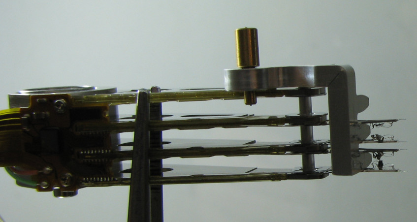
If the disc is subjected to an impact or a fall, the sliders are subjected to high stress, which can easily cause them to deform, thereby altering their aerodynamic characteristics. Consequently, the flight height of the heads above the platter surfaces and the parameters of the signal they read change, causing the signal processor to lose the ability to interpret the signal correctly.
Since the heads read not only user data but also the servo signal, which allows the current position of the heads above the platter surface to be determined, the deformation of the sliders also prevents this signal from being read correctly. And it is precisely the loss of the ability to interpret the servo signal and determine the position of the heads that causes the most typical symptom of mechanical damage – the characteristic clicking of the heads. This symptom results from the heads moving from stop to stop in search of the service area tracks – the area containing the firmware necessary to complete the initialisation process.
Head clicking is a very typical symptom of mechanical damage, but it can also result from other causes. This symptom will also occur in the event of demagnetisation (destruction of the signal recorded on the drive using a magnetic field) or an attempt to start the drive with a non-original EEPROM containing signal amplification parameters that do not correspond to the drive in question. In rarer cases, signal loss and clicking noises may also result from other firmware-related issues.
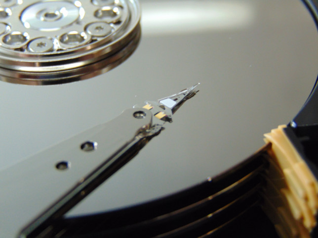
Another symptom indicating mechanical problems is failed attempts to spin up the motor. These are most often caused by the heads parking on the platter surfaces. Since both the heads and the platter surfaces are designed to be as smooth as possible, to cause minimal disturbance to the airflow inside the heat sink, and to minimise the risk of contact, if the heads park outside the ramp or parking zone, chemical bonds form between them and the platter surfaces, which block the platters from spinning up.
Motors damages
Far less common causes of the motor failing to start include seized bearings or damage to the motor windings. Bearing seizure was a fairly common fault in drives that used ball bearings; however, over 20 years ago, hydrodynamic bearings—which are much more resistant to damage—became widespread, and this type of fault has virtually disappeared. Damage to the motor windings is also very rare.
To diagnose the windings, their resistance must be measured. Depending on the drive model, this should range from a few to several dozen Ω. Generally, older drives are expected to have higher resistance than newer ones, 3.5” drives higher than 2.5” drives, and drives with more platters higher than those with fewer. In the event of an open circuit, the multimeter will indicate no continuity, and in the event of a short circuit, it will show a resistance of 0 Ω. If in doubt, it is best to measure the resistance of a similar working drive and compare it with the patient’s result.
Methods for repairing mechanical damage
Typical methods for repairing mechanical damage involve replacing faulty components with working ones. Magnetic head assemblies are usually replaced. Transferring platters to a different drive chassis only makes sense in the event of motor failure and, contrary to popular belief, this should not be done unless it is absolutely necessary.
The most common practical problem in repairing mechanical damage is the availability of suitable donor components. Due to the inability to purchase the necessary parts, it is necessary to buy suitable donor drives, and in extreme situations, to use magnetic head assemblies from damaged drives. The issue of selecting suitable donor components has been addressed only in a very fragmentary and imprecise manner. When selecting them, one can follow the guidelines available online; however, in practice it often turns out that heads which, in theory, are perfectly suitable for a given drive fail to read the signal correctly, whilst heads taken in desperation from a barely similar model allow data to be successfully recovered.
The difficulty in selecting donor heads is compounded by manufacturers’ policies, as they often sell technically different drive models under the same brand name. On the other hand, the interchangeability of components between seemingly very different drive models suggests that marketing and market segmentation sometimes have a greater influence on model designations than actual technical factors. An additional problem is manufacturers’ departure from the practice of using designations indicating the components used in the design, or the inconsistent use of such designations. For this reason, to verify the correctness of the donor selection, it is often necessary to swap the heads, and any failure often raises the question, rather than providing an answer, as to whether the heads are in fact unsuitable, or whether the signal reading problems stem from another cause.
Spin-Stand
These difficulties were identified some time ago and formed the basis for the development of a concept for disc-independent data recovery. This concept is based on a device that allows a platter to be mounted in a special device (spin-stand) and the signal to be read using a universal head, followed by the decoding and interpretation of this signal using appropriate software that emulates the operation of the drive’s firmware. The feasibility of such a process was confirmed in practice in 2006.
Research in this area, although it also included attempts to recover overwritten data in this way, was, however, pursued for only a very short time and concerned only drives that were already very old at the time and had very simple designs, even compared to the models of that era. Experience has shown that data recovery in this way, whilst possible, is highly complex and demanding in terms of technical expertise, particularly regarding signal processing, data encoding methods, and firmware solutions for defect management and addressing. Combined with expensive equipment, this approach was unable to compete economically with traditional methods, which, whilst not without their own problems, were simpler and cheaper.
Any attempts to develop a method for recovering data independently of the disc from modern drives would have to account for a number of additional complications associated with the introduction of perpendicular recording, which allowed for higher recording density whilst significantly degrading the signal-to-noise ratio. Furthermore, advances in the design of read/write heads and their positioners, as well as the emergence of two-dimensional magnetic recording (TDMR) call into question the possibility of creating a truly universal device capable of reading data from platters originating from any drive.
Additional challenges in developing a universal device include the eccentricity that arises when transferring a platter to a different mechanical subsystem, and the need to eliminate skew effects in high-density drives. Since it is not technically possible to assemble the drive with sufficient precision to avoid eccentricity, the servo signal is recorded after the drive has been mechanically assembled. Subsequent misalignment of the platter relative to the motor axis results in difficulties in tracking the track and frequent loss of the track, which significantly increases the time taken to perform operations.
Contamination and scratches on the surface of data storage media
Another mechanical issue is contamination or scratching of the storage medium. In the case of hard drives protected by metal casings, such problems may arise from deformation of the sliders, causing the heads to come into contact with the platter surfaces, or from improper interference with the mechanical subsystem carried out by unqualified personnel under unsuitable conditions. In the case of optical media, such as CDs and DVDs, contamination and scratching of the media most often result from improper storage and exposure to external factors. Such problems are much less frequently caused by random events, such as flooding.
Contaminated media must be cleaned before attempting data recovery to prevent further degradation. The choice of method and cleaning agents depends on the type of contamination. In doing so, the risk of mechanical or chemical degradation of the media must be minimised.
In the case of scratches, practical data recovery methods are heavily dependent on the nature and extent of the damage. In the case of hard drives, even minor scratches can be deepened and widened by the head’s contact with the platter surface. Any surface irregularity can cause the slider to lose its bearing force, which will press it against the platter surface and result in contact that may cause further damage. As a result, even minor scratches often develop into cylindrical scratches – characteristic scratches cut into the platter surface. The appearance of a cylindrical scratch can easily prevent data recovery, if not from the entire drive, then at least from the scratched area.
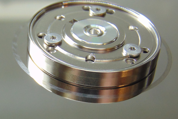
When the head is positioned over the scratch, it will fall into it and strike the surface, causing further damage by deepening and widening the scratch. As it rebounds off the surface of the disc, the slider begins to vibrate, leading to further contact with the surface. The head suffers mechanical and thermal damage from friction against the damaged surface, whilst simultaneously scraping material from it, which causes contamination of the interior of the enclosure.
The deepening of the scratch makes it difficult, and sometimes impossible, to withdraw the heads from it, whilst the metal filings floating inside the hermetic block contribute to the degradation of the remaining surfaces. In this way, symmetrical scratches can easily appear on all surfaces, making data recovery practically impossible. In extreme cases, operating a disc damaged in this way or contaminated internally may lead to the magnetic surface being completely ground down, making data recovery impossible not only practically but also physically.
Methods have been developed for cleaning, grinding, scratch-filling, surface levelling and polishing optical discs. In the case of hard drives, such an approach is considerably more difficult due to the significantly higher recording density. Furthermore, the dependence of the magnetic signal parameters on the distance of the heads capturing this signal affects the signal processor’s ability to interpret it. Therefore, any attempts to level the surface, fill scratches or apply a protective layer to the surface of a hard disc platter would require the firmware to account for changes in the distance between the head and the magnetic layer and to make appropriate corrections to the signal gain.
Methods for imaging the surfaces of data storage media
Virtually all practical methods of recovering data from hard drives and optical discs require the storage medium to be spun up. This means that damage preventing the medium from rotating, such as breakage, bending or perforation, effectively makes data recovery impossible, although in a physical sense the data is still largely recoverable. To recover data from such damaged media, it is necessary to image their surface, and then extract the recorded signal from the image and decode it.
In the case of optical media, it is necessary to image the burned (or embossed) and unburned (unembossed) sections of the track, and in magnetic media – the magnetisation of the surface. Therefore, for damaged CDs and DVDs, imaging using optical microscopes is appropriate, and for hard drives – magnetic force microscopy. This does not mean that attempts were not made in the past to reconstruct the surface magnetisation using optical methods.
For decades, the method developed by Francis Bitter in the early 1930s, which utilised a colloidal suspension containing magnetite particles, was used to visualise surface magnetisation. After applying the suspension to a magnetised surface, the magnetite particles align along the domain walls, allowing the position of the magnetic domains to be observed using an optical microscope. A limitation is the resolution of optical microscopes, which, even in the 1990s, with the increasing recording density on hard discs, proved insufficient.
Another concept involved the use of the Kerr and Faraday magneto-optical effects, which involve the deflection of polarised light under the influence of a magnetic field. The Kerr effect is observed when light is reflected from a magnetised surface, whilst the Faraday effect is observed when light passes through a magnetised medium. Therefore, in the case of magnetic media, the Kerr effect can be observed directly, whilst observation of the Faraday effect requires the use of a transparent medium with ferromagnetic properties – a ferrogranate crystal. However, the resolution of these methods ceased to be sufficient for hard drives as early as the 1990s.
Therefore, the only viable method for recovering data from severely damaged hard disc platters is magnetic force microscopy. The history of hard disc research using magnetic force microscopes dates back to the late 1980s and early 1990s, and these studies were originally focused on recovering overwritten data. Ultimately, the research demonstrated that it was not possible to recover overwritten data, but confirmed the practical feasibility of recovering data from mechanically damaged platters, including those shredded by specialised hard drive shredders.
Imaging the magnetised surface is only the first step in the data recovery process. Subsequently, the acquired images depicting the magnetisation of the platter fragments must be pieced together, and only then can signal analysis be carried out. The more such fragments there are, the more complex the task becomes, especially if the imaged fragments include those originating from other drives.
And it is the complexity of the task—which involves separating fragments from the actual drive from those originating from other media—that makes it extremely unlikely that data will ever be practically recovered from a shredded drive. However, it is quite feasible to recover data from drives damaged in a less severe manner, such as scratches and gouges on the surface that cause damage to the read/write heads when attempting to read data using traditional methods. This also applies to drives damaged intentionally, e.g. drilled through, pierced with nails, smashed with a hammer, or with bent or cracked platters caused by screwing a long screw into the appropriate place on the casing (the so-called ‘red dot’ method) or in any other way.
Firmware faults
As recently as 20 years ago, firmware failures in data storage devices were rare. Since then, however, much has changed, and technological progress has led to a significant increase in the complexity of firmware, which has contributed to a rise in its susceptibility to failure. This category of faults is particularly significant in the case of solid-state drives, accounting for almost all their failures, and in SMR drives.
The most common symptoms of firmware faults are:
device suspension (no response to commands, no data exchange, BSY bit set in the status register, computer suspension for 20–30 seconds when attempting to boot with the faulty storage device connected),
incorrect model detection (so-called technical passport; instead of the model name specified by the storage device manufacturer, a name typical of the controller appears, e.g. SATAFIRM S11 for an SSD on a PS-3111 controller, sometimes diagnostic messages also appear in the technical passport – for example, serial numbers in SSDs on Intel controllers were replaced with error codes),
detection of zero or very low (a few to several dozen MB) capacity,
in some cases, the drive initialises correctly and comes up ready, displaying the correct capacity, but all LBA sectors read as empty or containing errors.
In the case of hard drives, they appear to be functioning normally; the initialisation process proceeds correctly until the service area is located, at which point it either halts during error handling whilst reading it (suspending) or proceeds to the end, though without allowing access to LBA addressing (entering standby mode without the ability to read data). The heads do not click, with rare exceptions in WD SMR drives, where, in the event of second-level translator (T2) damage, temporary noises resembling problems with reading the servo signal and losing the track may occur. In Seagate F3-generation drives, a capacity error of 4 GB, usually preceded by a few seconds of head clicking and motor stalling, indicates mechanical damage requiring replacement of the magnetic head assembly. Attempting to repair the firmware on such a drive without first replacing the heads risks worsening its condition.
SSDs usually suspend or behave in a manner characteristic of the specific controller. The controller emits heat similar to that emitted by controllers of this type in functional devices. SSDs with firmware damage generally enter standby mode and allow for limited communication after being placed in so-called Safe Mode. This is usually done by short-circuiting the relevant control points on the PCB.
Portable semiconductor storage devices are usually detected by the operating system. A message appears indicating that they have been detected, but with zero capacity. Often, a message also appears stating that there is no storage device in the device. Diagnostic programmes usually correctly identify the controller model (sometimes only its ID), and often the memory ID as well.
Firmware issues are, in theory, always solvable, but in practice they often pose serious difficulties. Apart from the issue of the uniqueness of the modules most prone to damage, a common problem, especially in newer storage devices, is the protection of the firmware against external interference and encryption. Another obstacle may be the physical degradation of the storage medium, which makes it difficult to write the corrected modules onto it.
Firmware damage rarely affects the executable code; instead, it most often involves incorrect entries in various logs or parameter tables essential for the drive to function correctly. Such damage may result from errors or distortions when changes are written, a sudden power failure during writing, physical degradation of the medium in areas designated for storing service information, or the overflow of the area designated for recording specific information. The key problem in repairing firmware faults is that they usually concern information unique to a given media unit, which cannot be replaced with information from another device.
Firmware errors most often concern the subsystem that translates LBA addresses to physical addresses, which is critical for accessing user data. For this reason, before attempting to repair errors of this type, it is essential to secure the initial state and exercise particular caution so as not to make the situation worse. In particular, the loss of even damaged original fragments of the firmware and their replacement with other content can be critical for the subsequent data recovery process.
In SMR and SSD drives, in some cases, damage to the translator manifests itself in the drive being detected correctly, with the correct model and full capacity, but with all sectors set to zero. In most cases, this symptom indicates that the data has been destroyed by being overwritten; however, there is another possibility. Due to errors in the translator, the drive does not physically read the contents, but simply returns zeros in response to a command to read any sector.
In such a situation, it is worth checking whether any content can be read at the physical address. Switching to physical addressing may allow for at least partial data recovery even in the event of an incorrect implementation of the Secure Erase procedure. In some cases, the Secure Erase operation amounts to writing the appropriate information into the translator tables without physically destroying the data.
Other common errors relate to overflowing SMART (Self-Monitoring, Analysis and Reporting Technology) logs and lists of unstable sectors. As this information is not critical for booting the drive or accessing data in these cases, the problem can often be resolved by clearing the overflowing modules. Less common are faults in software components, which can simply be copied from a drive with the same firmware version, or configuration modules, which can be copied and used after minor and relatively simple modifications.
The category of firmware issues often also includes storage capacity limitations imposed by the HPA (Host Protected Area) or DCO (Device Configuration Overlay) functions. Often, this limitation is not a fault in the strict sense, but is used deliberately for maintenance, operational purposes or to conceal data. However, sometimes such a capacity limitation may arise spontaneously as a result of software errors. A popular example of such a fault until recently was the limitation of 1 TB drive capacity to 32 MB (0xFFFF sectors) by the BIOS (Basic Input–Output System) on Gigabyte motherboards.
Given the wide variety of faults that can occur, the diversity of firmware architectures, and the differences between individual model families and firmware versions, these faults always require thorough diagnosis and a clear understanding of the problem before attempting to resolve them. In particular, it is risky to hastily click through the automated procedures provided by advanced data recovery software. Such procedures have been designed with the most common problems in mind, which ensures they are fairly effective, but offers no guarantee that a specific problem falls into the category of the most common ones.
In the case of hard drives, it is good practice to back up all available copies of the service area’s contents. It is often possible to reconstruct damaged sectors by piecing them together from correctly read sectors of the damaged copies. Sometimes it is necessary to utilise dependencies, e.g. between the translator and the defect lists. In extreme cases, one can attempt to fill in the missing fragments manually.
If it is not possible to save the corrected modules to the service area, you can attempt to perform a partial initialisation of the disc and load the corrected modules into RAM (Random Access Memory) from a file. On some drives, a Hot-Swap procedure can be performed. This involves writing the corrected contents of the service area to another, sufficiently similar drive. The drive is then booted, put into sleep mode and, whilst connected to the power supply, the PCB with the firmware fully loaded into RAM is transferred to the patient.
For semiconductor storage media, there are numerous tools available for repairing them in the event of firmware damage. Unfortunately, there is still a widespread belief that the best way to recover data is to repair the device. These programmes work by initialising the NAND Flash memory, erasing all physical blocks, scanning them for defects, and creating new Flash translation layer tables. This procedure irreversibly destroys the data and, due to the physical degradation of the memory chips, cannot guarantee the long-term functionality of the storage medium after repair.
Until recently, a very popular method of recovering data from semiconductor storage media involved desoldering NAND flash chips, reading them on a programmer, and then decoding the binary images obtained in this way and reassembling them into a logical structure. This method essentially involved recreating and emulating the operations performed by the storage controller. However, with the increasing mathematical complexity of the algorithms used and the widespread adoption of encryption, this method began to lose its relevance. In particular, encryption effectively prevents its meaningful use in practice.
The second, increasingly popular approach involves putting the storage device into safe mode and loading a specially prepared program – a loader – into its RAM. A storage device started in this way allows the execution of technical commands that enable the reconstruction of the firmware, including the translation subsystem, and the retrieval of data. The main problem with this method is its complexity and the need to carry out reverse engineering research separately for each controller, and typically for each firmware version.
For this reason, the practical application of this method is usually limited to the use of loaders provided in commercial tools. The workload, time and economic constraints required to develop a suitable tool mean that only a small group of the most popular controllers are supported in this way. An additional problem is the progress made in securing storage media against encryption cracking, making newer models more resistant to known attack methods.
Due to the small number of centres conducting serious research into data storage media in terms of their faults and data recovery capabilities, progress in this field is failing to keep pace with the growing number and complexity of the problems encountered. Given how increasing storage density necessitates the introduction of successive, increasingly complex solutions for error correction, defect management, data addressing and media optimisation, without a significant increase in research into these issues, the gap between what is physically possible and what is practically feasible will only widen. For this reason, we are increasingly encountering situations where, for practical reasons, data that is physically recoverable is not recovered.
Degradation of the data storage medium
A common cause of data storage device failure is degradation. In such cases, the device initialises correctly, enters a ready state and allows access to LBA addressing. However, when attempting to read the contents, problems arise, such as very slow read speeds, corrupted files, frequent execution of file system integrity checking tools such as chkdsk, scandisk or fsck, bad sectors, and warning messages from the SMART subsystem, and, in the case of hard drives, also noisy operation and unusual sounds from the read/write heads.
The degradation of the storage medium’s condition can be verified using a scan with diagnostic software. These programmes check access times to individual LBA sectors regardless of their content and addressing within the logical structures of file systems. If errors are detected, good diagnostic programmes will return information about the type of error retrieved from the error register.
During diagnostics, it is worth paying attention to the type of read errors, as sometimes the drive is not actually degraded and the cause of the read errors lies elsewhere. For example, ABRT (command refusal) errors are often linked to the drive being protected via ATA-Password. Sometimes, a very high number of read errors alongside fast and quiet drive operation may result from translator issues. In the case of Seagate drives, this situation results in UNC (checksum error) errors, and in the case of WD drives – IDNF (invalid sector identifier) errors.
In SSDs, defect management algorithms usually effectively remove damaged blocks from use, and such blocks are rarely detectable by scanning. Their detection during a scan usually indicates that the SSD’s condition is already critical. When diagnosing SSDs, it is worth paying attention to read times. Instability and very slow read speeds usually indicate a high degree of wear on the memory chips.
Due to the risk of further damaging degraded storage media, care must be taken during the diagnostic process not to place excessive strain on the media. In most cases, data recovery does not require full knowledge of the condition of the storage medium’s surface, and there is no need to risk exacerbating the fault in order to obtain this knowledge. As the scan involves reading successive sectors, once you have a general understanding of the disc’s condition, it is advisable to proceed with a sector-by-sector copy as soon as possible. It is worth remembering that a sector-by-sector copy can also be made in sections, and if more degraded areas are encountered, they can be skipped in order to first secure the contents of sectors that are easier to copy, and return to the more difficult ones later.
In principle, data stored in damaged areas is impossible to recover, but not everything is so clear-cut. With the recording densities achieved today, it is practically impossible to write and read data without errors. Therefore, every physical allocation unit on every storage medium is protected by error correction codes (ECC). These codes allow errors to be corrected and the correct content to be read, though their correction capabilities are limited. A read error occurs when the number of bit errors exceeds the correction capabilities of the code used.
In some cases, the number of bit errors only slightly exceeds the code’s correction capacity. This opens up the possibility of making further attempts to read sectors that proved unreadable on the first attempt. It should be borne in mind, however, that many factors can influence read errors, such as the stability of the supply voltage or thermal fluctuations, and controlling these factors can improve read performance.
In particular, the quality of reading from Flash-NAND memory chips can be improved by controlling the temperature at which the read operation is performed. It is also worth testing the feasibility of using supply voltages that are lower or higher than the nominal values. In the case of hard drives, however, changing the position of the drive during reading can sometimes help.
There is no single approach to such situations. In each case, measures to improve read quality should be selected experimentally, whilst monitoring the results. At the same time, sudden changes should be avoided in order to minimise the risk of further deterioration or causing more serious damage to the medium.
Logical structures faults
Logical damage occurs in situations where the storage medium, as a technical device, is in working order, but errors in the logical structures prevent access to the data, or where errors in the logical structures result from damage to the storage medium, such as its degradation. Particularly in the second of the cases mentioned above, logical problems are best resolved by working on a previously made copy, in order to limit the strain on the original storage medium and the risk of its condition deteriorating. Logical damage may include partition tables, file system metadata or errors within the files themselves.
Generally, content lost either as a result of read errors or replacement with other data (overwriting) cannot be recovered. However, it is often possible to reconstruct and repair logical structures using copies of metadata and mathematical relationships between individual parameters. Many such problems can be automatically repaired by data recovery software, whilst others must be resolved manually.
The fact that even advanced tools are unable to locate certain traces, return incomplete results or recover corrupted files does not mean that what could not be found by automated means does not actually exist. A significant limitation of data recovery and digital forensics software is that, when identifying objects, they rely on predefined signatures, and even a minor discrepancy (e.g. a bit error) can result in something being omitted from the results, something that can easily be spotted by viewing the contents of the storage medium in a hex editor. Furthermore, automated tools perform very poorly with fragmented files.
A significant obstacle to accessing data is often the encryption of the storage medium’s contents. In addition to the aforementioned hardware-level encryption, typically covering the entire disc (FDE – Full Disk Encryption), we may encounter partition-level encryption (FVE – Full Volume Encryption) or file-level encryption (FBE – File-Based Encryption). Furthermore, data on the drive may be hidden within encrypted containers, which are not necessarily visible in the logical structure (e.g. TrueCrypt or VeraCrypt).
Since the encrypted data does not match any predefined signatures, data recovery and digital forensics tools are unable to identify any meaningful content within the encrypted data stream. The fact that a storage medium or part of it has been encrypted can be established with a very high degree of certainty on the basis of the high-entropy data stream filling it, which is easily noticeable in a hex editor. In theory, encrypted data is fully recoverable; however, a practical prerequisite for decrypting it is the possession of the encryption key.
Most often, the encryption system is compromised by locating the storage location of the encryption key or discovering a method that allows for its unauthorised forced use. Due to the length and high entropy of encryption keys, brute-force attacks directly on the key are unlikely to yield results within a reasonable timeframe and are of no practical significance. However, attacks on PINs and passwords securing access to the key may be worthwhile. Such security measures are usually shorter and simpler, and are often vulnerable to dictionary attacks.
A major limitation of manual analyses is that they are time-consuming and labour-intensive; given the capacity of modern storage media, this practically rules out the possibility of conducting a thorough analysis within the constraints of time and budget. It is therefore inconceivable for a specialist to work effectively without using the appropriate tools. Nevertheless, this work should not be limited to scanning and automatically generating a report, but should be supplemented by verification and in-depth analysis of the results. For this reason, data recovery and computer forensics specialists should possess the necessary expertise in understanding the logical structures of file systems and the practical use of a hex editor.
Principles for securing data storage media and their contents
The basics of data storage preservation and data recovery
When undertaking the preservation of digital evidence, it is difficult to foresee in advance all the problems that will need to be resolved in order to gain access to the data. It is therefore important to proceed with caution, minimise the risk of errors, avoid excessive interference and refrain from taking unjustified actions. In striving to secure as much of the available information as quickly as possible, it is important not to overlook the risk of failure and deterioration of the storage medium, and consequently to avoid interventions that would preclude the use of other measures.
It is best to work with storage media at a prepared workstation, equipped with all the necessary tools and a computer with the required software installed. The TRIM function must be disabled on the computer used for data recovery. It is best to connect the drives via hardware write blockers or specialist data recovery controllers. It is essential to protect them from being overwritten, whether accidentally or intentionally (e.g. initialising the drive in response to a prompt from the operating system).
Working at makeshift workstations and in field conditions should be treated as a last resort and undertaken only in exceptional circumstances. Similarly, attempts at remote data recovery should be avoided. Apart from the fact that, for security reasons, it is advisable for computers used for data recovery to be disconnected from the network, factors that are difficult to observe remotely, such as the sound of the hard drive or the temperature of the storage medium, are of great importance in the data recovery process.
In general, the data recovery process can be divided into the following stages:
- diagnostics,
- gaining access to the storage medium,
- creating an image of the storage medium,
- reconstructing the logical structure,
- recovering files,
- extracting the information contained in the files.
The sequence of the individual stages and the necessary steps in a specific case is determined by the nature of the fault. It should be borne in mind that certain actions and interventions, whilst technically justified, may be inadmissible on procedural grounds and may lead to the formal challenge of evidence that has not been properly secured. For the same reason, it is also essential to document the actions taken appropriately.
Diagnostics
When undertaking a diagnosis of storage media, it is advisable to gather as much detailed information as possible about the device, its condition and contents, as well as any circumstances surrounding the damage. It should be borne in mind, however, that the reliability of such information is limited. Firstly, the people handing over the storage device for analysis, or those in whose care the device is being kept, may not necessarily have the relevant knowledge about the device or the expertise to describe its condition in sufficient detail and with sufficient precision. Secondly, they may have an interest in deliberately misleading law enforcement, the judiciary and analysts.
When securing data storage media, the most important thing is to prevent their condition from deteriorating. It should be borne in mind that actions may have been taken against them to prevent access to the information. Before proceeding with any actions, the media should be carefully inspected for mechanical, thermal or electrical damage, signs of water damage and corrosion, and other possible tampering.
Media must also be protected against secondary damage during transport and storage. It is important to bear in mind that a number of devices, particularly mobile ones, may still be able to communicate wirelessly, including receiving and executing commands designed to delete their contents or lock them down. For this reason, it is necessary to physically prevent such devices from communicating with the outside world.
If any damage is noticed, it must be repaired before the storage medium is powered up. Storage media showing signs of water damage, corrosion or thermal damage should not be powered up; in the case of hard drives, this also applies if there is any suspicion that the enclosure has been opened, without first carrying out a detailed inspection of its condition. In the case of hard drives, it is particularly dangerous to start them up with any contaminants inside the enclosure, missing or excess components, bent sliders or broken heads, as these can lead to the destruction of the magnetic surfaces of the platters.
The diagnosis of data storage media is too broad a topic to be described in detail here. When carrying out such diagnostics, one should rely on an understanding of the design and operating principles of the devices, as well as their boot procedures. It is also worth paying attention to the most typical symptoms of individual faults, as described in the previous section. Diagnostics should be approached with caution and precision, avoiding a routine approach and preconceived assumptions, even if statistically such assumptions often prove correct.
Accessing the content of the medium
Gaining access to the media’s contents often requires rectifying faults identified during diagnostics. In many cases, it is necessary to replace faulty electronic components or entire sub-assemblies, such as the magnetic head assembly. In other situations, it is necessary to interfere with the firmware, including removing or bypassing security measures. When interfering with the firmware, it is important to back up the initial state so that you can revert to it if the changes made do not produce the desired result.
In the case of damaged semiconductor media, there are two main approaches to retrieving their contents: working in so-called safe mode and reading the contents of desoldered memory chips on a programmer. It is worth noting here that in the case of encrypted storage media, the second approach is pointless, whilst in other situations the first is usually easier, less labour-intensive and yields better results. For this reason, priority should typically be given to attempts to establish relatively stable communication with the storage medium, and only subsequently should desoldering be considered. When soldering memory chips, care must be taken not to overheat them or damage the pins.
If the SSD in question is in working order and data has been deleted from it, this drive must also be put into safe mode. All modern SSDs support the TRIM function, which ensures that deleted files immediately disappear from the LBA address space and the process of physically erasing them begins. This process is carried out by the drive’s firmware independently of other commands received from outside, and even connecting the drive via a hardware write blocker cannot stop the physical erasure of the blocks. The erasure of blocks can be halted by putting the drive into safe mode and keeping the controller busy with read commands for the data being sought in the physical address space.
Imaging of the media
A disc image (clone) can be created on another disc or as a binary file. Each of these options has its own advantages and limitations, and it is difficult to say definitively which is better. The decision on where to clone the disc image is made based on the nature of the task, applicable internal procedures, available infrastructure, and the operator’s personal preferences.
In the past, the standard practice was to create a binary copy of the storage medium as a whole, but the widespread use of encryption has necessitated a change in this approach. Creating an image of an encrypted storage medium that cannot be meaningfully analysed is pointless. Therefore, in the case of encrypted media, the current aim is to unlock the device, break the encryption and obtain an image of the decrypted partitions, rather than a raw image of the encrypted contents of the media.
The resources and tools required to create an image of a storage medium depend largely on its technical condition. For functional storage media, the Linux `dd` command or simple, widely used, free disc cloning software is entirely sufficient. In digital forensics, various types of duplicators are commonly used, allowing, amongst other things, the cloning of devices with a degraded surface and ensuring appropriate handling of read errors, whilst simultaneously acting as a write blocker on the source drive.
For the most complex and unstable cases, including parts of discs following head replacement, it is advisable to use specialist controllers that work in conjunction with data recovery software. Such controllers are also used in many cases of firmware damage. The software for operating such controllers allows for a wide range of interventions, including modifying the contents of the drive’s RAM buffer, loading appropriately prepared content from a file into it, or building a virtual translator.
When recovering data from desoldered Flash-NAND chips, it is necessary to decode the data, correct it using ECC codes, and separate the user data from the redundand information. Next, the physical allocation units must be assembled in logical order to obtain a coherent image of the logical structure. In theory, this task can be performed using any hex editor; however, its complexity means that specialised software is used for effective work.
Whilst creating an image of functional drives presents no difficulties and carries no risk, in the case of damaged devices, one must take into account the possibility of further deterioration and adapt the cloning approach to the specific nature of the task. In particular, one may aim to clone as much of the content as possible, bypassing the most problematic areas and returning to them later. It is worth remembering that cloning can be performed in stages, and the decision on which sections to clone next can be made based on an analysis of previously cloned data. In doing so, one should avoid burdening the drive by re-cloning areas that have already been cloned.
In particular, it is advisable to start by cloning the metadata areas of the file systems and to decide to clone selected partitions first – those potentially containing the most relevant material – and only then move on to partitions with potentially less significant content. Depending on the needs and specifics of the task, one can focus on cloning either the occupied (allocated in logical structures) or free space first, or proceed immediately to searching for particularly important files, such as databases. When creating an image to binary files, the fragments cloned in this way must then be reassembled into a whole.
When creating a sector-by-sector copy, it is worth paying attention to areas where data may have been hidden. These may include, for example, the areas between the start of the disc and the first partition, at the end of the disc, or the gaps between partitions. It also happens that data is hidden in the end areas of the disc, which are later excluded from LBA addressing using the HPA or DCO functions and become invisible to operating systems and most programmes.
Once the image has been created, it is advisable to make an additional copy of it so that further operations can be carried out on the copy. This helps to avoid having to repeat the cloning process in the event of a failure or human error. Once cloning is complete (i.e. a full copy of the storage medium has been made, everything that is technically possible has been cloned, or the process has been terminated if it is deemed pointless to continue), a hash function is usually calculated for the acquired image. It is also common practice to record the timestamps of the image creation.
Reconstruction of the logical structure
The first step in reconstructing the logical structure usually involves using automated procedures within data recovery software. Programmes of this type are capable of analysing the fragments of file system metadata found and using them to reconstruct logical structures and virtually fill in missing elements and values, e.g. based on a copy of a given structure or known interrelationships between certain structures. Given that the logical structures of individual file systems are fairly well known, the algorithms of reputable data recovery programmes are very similar and produce comparable results.
A weakness of automated algorithms is that they generally cannot fill in missing values or correct obviously incorrect parameter values, nor can they make complex decisions in terms of probability under conditions of incomplete information. In such situations, the operator may attempt to construct a virtual partition by setting the appropriate parameters for the programme based on their own knowledge and experience, or achieve the desired result through trial and error. In certain situations, it is justified to intervene in damaged file system metadata, which may directly lead to the repair of the logical structure or enable data recovery programmes to locate or organise a greater number of files within the directory structure.
Given the procedures for securing digital evidence, such interventions could lead to the evidence being formally challenged. Therefore, they should be carried out on an additional working copy, and the relevant analyses should be conducted on that copy; only once the results are available should one return to analysing the evidence. One should also be wary of drawing far-fetched conclusions and tailoring results to fit a preconceived theory, such as forcibly matching found metadata fragments containing names and timestamps to the files found.
Such matching may, of course, be justified in certain situations if supported by the file size and its location sufficiently matching the description in the metadata. For certain file types, it is also possible to compare the timestamps contained in their internal metadata (e.g. Exif) with the timestamps describing the file within the file system structures; however, it must be borne in mind that, for many reasons, these values may differ. It should also be borne in mind that whilst such actions are entirely justified from a technical point of view and are practised in data recovery, they may be inadmissible for procedural reasons in various types of legal proceedings.
Another popular method for reconstructing the logical structure of a file system — though not recommended due to the risk of further damaging the metadata — is to use system tools such as chkdsk, scandisk or fsck. These tools analyse the file system’s metadata, identify errors and remove them. However, the word ‘remove’ should be taken quite literally – damaged fragments are usually removed so that they do not prevent the operating system from mounting the partition.
Removing damaged metadata segments may not only lead to the misplacement, corruption or irreversible loss of a larger number of files, but also destroys information that could be analysed and used to draw conclusions to aid in the manual reconstruction of the file system. Furthermore, procedures of this type perform uncontrolled writes to the disc, which not only constitute an unacceptable interference with its contents but are also practically irreversible. Therefore, the use of such procedures should be restricted solely to situations where they can assist in mounting a partition and booting an operating system requiring ‘live’ analysis, and only provided that the initial state has been secured beforehand. It is also important to ensure that the media being secured are protected against the accidental automatic execution of such procedures.
File recovery
In most cases, reconstructing the logical structure of the file system allows the files stored within it to be recovered. Under certain conditions, depending on the type of file system and its internal architecture, it is often also possible to recover some of the deleted files within the directory structure, retaining their original names, timestamps and other attributes supported by the file system (e.g. ownership). This is the most desirable outcome; however, due to technical faults, logical errors and deliberate counter-detection measures, it is not always achievable. Furthermore, the fact that something has not been found and addressed within the logical structure does not necessarily mean that it does not exist.
In cases where metadata damage partially or completely prevents the reconstruction of the file system’s logical structure, or where the metadata of deleted files has been destroyed (e.g. inode entries in Unix-based file systems), lost files can be sought using their signatures (RAW search). The names of files recovered in this way differ from the original, lost names and are assigned automatically by data recovery software. Typically, these names are based on the sector number in which the file header was found; occasionally, they may be supplemented with certain details based on the file’s internal metadata.
A RAW search may return many junk results (random matches between a string of characters and the signature pattern), corrupted files (e.g. fragmented or partially overwritten with other content), and duplicates of files correctly located within the directory structure. In the case of the latter, the clutter created by a RAW search can be reduced by limiting the scan to the unallocated space in the file system. Scanning the unallocated space in the file system may also yield interesting results on computers where the operating system has recently been reinstalled. Provided, of course, that the data has not been destroyed by overwriting or in some other way, e.g. by the TRIM function.
Furthermore, not every file type has a signature that allows it to be found via a RAW search, or the signature may be corrupted. For this reason, it is worth attempting to locate potentially relevant strings of characters using the search tool. These may include, for example, personal or contact details of individuals involved, or terminology related to the nature of the case. This method can recover not only lost files, but also fragments of files that were deleted long ago and partially overwritten.
When using a search engine, it is worth bearing in mind the various data encoding methods and trying searches using both ASCII (American Standard Code for Information Interchange) and Unicode. In the case of ASCII encoding, there are code pages – different sets of graphic characters for codes in the range 0x80-FF, allowing, amongst other things, for the encoding of texts in non-Latin alphabets. Particularly in the case of cross-border crime, selecting the appropriate code page may reveal that a seemingly meaningless string of symbols is in fact text in a foreign language.
Retrieving information contained in files
Extracting information from recovered files — provided they are not encrypted or password-protected — is generally a straightforward task in the case of intact files. To access their contents, all you need is the right software. However, with certain categories of devices, we may encounter specific file formats, methods of encoding audio and video material (e.g. in various types of recorders), and even specific file systems (automotive electronics, Internet of Things devices, drones). In such cases, it is best to have the appropriate software from the device manufacturer; if this is not available, reverse engineering analysis is necessary.
Another issue is file corruption resulting from physical read errors or partial overwriting. In such cases, the course of action depends on the file type. For some popular file types, repair tools are available. However, it should be borne in mind that these tools are only capable of repairing relatively minor errors and will not be able to recover significant missing or damaged sections of the file.
Damaged audio and video files can often be played back, although there will be audio and video distortion at the points of damage. In such cases, it is worth trying out several different players, as, depending on the encoding and compression algorithms used, some may perform better than others. A particular cause of faults in video files recovered from formatted memory cards is their fragmentation, which causes data recovery programmes to link headers to the wrong files. Such files can be repaired by correctly linking the headers to the correct files using a hex editor.
In the case of damaged unencrypted and uncompressed files, such as a significant proportion of databases, *.xml files, software source code, bitmap graphics, or older types of office suite files, it is possible to read a significant portion of the text, numerical values, or database records using various types of editors. The content recovered in this way will not be complete, but may contain information significant enough to warrant undertaking this type of analysis. In the case of databases, missing records can often be supplemented from backups or older versions of files, which are frequently stored in a subdirectory such as ‘Archive’ on the same drive.
Ransomware attacks are a specific cause of file corruption. To corrupt as many files as possible as quickly as possible, the malware typically limits itself to encrypting the initial section of the file containing its header. In the case of database files, it is often possible to repair the file (usually with minimal loss of data) by restoring the correct header. Another way to decrypt infected files is to use decryptor databases available online, e.g. nomoreransom.org.
Without delving into the legal and moral implications of such a decision, it is also possible to pay the ransom to the criminals, either directly or through numerous companies offering to decrypt the infected files. Leaving aside the fact that we do not have a sufficient number of suitably qualified cryptanalysts to support the existence of such a large number of companies offering this type of service, the results of such services appear far too quickly compared to the time that would be required to achieve them using cryptanalytic methods without cooperating with the criminals. Furthermore, these companies, aside from the illusion of not paying the ransom, issue a standard invoice for the service, which for many victims is an attractive solution to the problem of accounting for the bitcoin sent to the ‘тридевятый паханат’/*, and also reduces the risk of the data not being decrypted despite the ransom being paid.
Files can also contain other data that is not consistent with the file type. Image files are particularly often used to carry hidden data, such as malicious executable code, but also hidden information. They are highly resistant to having foreign content embedded within them, and this content can easily go unnoticed unless it causes the file size to increase to a noticeable extent. Data can also be hidden in audio or video files in a similar way. This is particularly true of the latter, as there is no need to worry too much about large file sizes.
Another method of hiding information involves the alternative data streams of the NTFS (New Technology File System). These are typically used to store brief information about a file, such as its origin, and are resident in the $MFT (Master File Table) file; however, they can also describe a completely different file located in specific clusters of the partition. From a practical point of view, NTFS alternate data streams are additional, named $DATA attributes (0x80) and their presence is easily detected by examining the $MFT record describing the file in question.
Another aspect worth noting is steganographic techniques designed to conceal not only the content but also the very fact that certain information exists. The most popular steganographic technique is the Least Significant Bit (LSB) technique. It utilises image, audio or video files and involves modifying the least significant bits encoding the image or sound to conceal secret information within them. Detecting this technique is difficult, as the modified file opens correctly, and the modifications distort the image or sound so imperceptibly that it is practically impossible for an unwitting recipient to detect.
Another counter-detection technique involves changing file signatures and extensions, and placing them in locations where their presence may go unnoticed. Changing the signature to one other than that appropriate for the file type in question, particularly to a meaningless string of characters, protects it from being found by automated data recovery programmes. Conversely, giving the file an inconspicuous name, changing the extension (e.g. to *.dll) and placing the file in one of the operating system’s directories minimises the risk that an analyst will take an interest in it during manual analysis, for example following a failed attempt to open a file disguised in this way.
/* тридевятое (or тридесятое) государство (царство, королество) - a distant, fairy-tale land lying "beyond the mountains, beyond the forests". Паханат (from пахан - leader of a criminal group) - a land ruled by a criminal.
Conclusion
The physical possibilities for data recovery extend far beyond the results achieved using currently available tools and commonly known methods. However, harnessing this potential would require systematic research in selected areas, which in turn would necessitate viewing the issue of data recovery from a long-term perspective, adopting a comprehensive approach, and consistently securing funding for subsequent projects. It is difficult to expect such research to be undertaken in the foreseeable future.
In reality, pushing the boundaries of what is practically feasible towards what is physically possible must be done in small steps. Such a step could be any departure from the beaten track, seeking a solution to a problem where running through automated procedures yields no results, conducting manual analyses, and verifying the results returned by available tools. It is worth undertaking such actions, because often even a small amount of extra effort yields significantly better results, and in certain situations it is solely down to the operator’s diligence and skill whether any results appear at all.
To improve the effectiveness of data recovery, it is essential to understand how data storage media work and their logical structure. These form the basis for effective diagnostics, which in turn significantly influences the selection of appropriate methods to resolve the problem, increases the chances of a successful outcome, and minimises the risk of errors and unnecessary intervention. This understanding also allows one to distinguish between what is truly impossible and what is merely difficult.
Unfortunately, data recovery is a heavily neglected and underestimated field, and as such requires a significant investment of self-study and hard work. Analytical skills, as well as proper verification and selection of learning materials, are essential here. All the more so because false, and sometimes even harmful, information can be found not only on low-quality online forums but also in school textbooks.
The importance of understanding, gaining experience and improving one’s skills is all the more significant given that errors in data recovery are often irreversible. For this reason, one should use drives that contain no important data for learning and experimentation, avoiding risky actions on drives containing vital data, particularly evidence. Given the diversity of data storage media models, design solutions and firmware, as well as the faults that occur in them, one cannot expect anyone to be able to avoid mistakes entirely; however, every available means should be used to minimise the risk of errors.
Developing understanding, experience and independence in data recovery is also of significant importance in the context of widely used highly advanced tools, and particularly their origin. One must be aware that such advanced tools are largely commissioned, developed, and maintained in collaboration with and under the control of intelligence services from states that are not necessarily allies, and in some cases are even openly hostile. Some of these companies were founded and are run by intelligence officers (even if formally former ones) and employ officers as key personnel. This is particularly important when using manufacturers’ technical support, as granting remote access to a technician may be tantamount to inviting a data leak.
Acquiring reliable technical knowledge about data storage media is of critical importance for specialists directly involved in data recovery, but a basic understanding of these issues is also important for officers securing devices for transfer to the laboratory. A general understanding of this subject will also be useful for line managers and prosecutors supervising proceedings, as unrealistic expectations based on various myths and legends do not aid the work and often lead to disappointment.
Bibliography
1. Amer, A., Holliday, J., Long, D. D. E., Miller E. L., Paris, J-F., Schwartz, T. S. J.: Data Management and Layout for Shingled Magnetic Recording, „IEEE Transactions on Magnetics”, 47(10), (2011).
2. Baraniecki, P.: Czas (nie) jest najprostszą rzeczą, Zwalczanie Przestępczości Internetowej, Sanok (2025),
3. Baraniecki, P.: Smartfon i „biling” nie są jedynymi źródłami informacji [w] Matyniak, G. [red.] Zwalczanie przestępczości internetowej, Uczelnia Państwowa im. Jana Grodka, Sanok (2025),
4. Bertram, H. N.: Theory of Magnetic Recording, Cambridge University Press, London (1994),
5. Bitter, F.: Experiments on the Nature of Ferromagnetism, “Physical Review” 41(507), (1932),
6. Chan, K. S., Radhakrishnan, R., Eason, K., Elidrissi, M. R., Miles, J. J., Vasic, B., Krishnan, A. R.: Channel models and detectors for two-dimensional magnetic recording. “IEEE Transactions on Magnetics”, 46(3), (2010),
7. Chen, B. M., Lee, T. H., Peng, K., Venkataramanan, V.: Hard Disk Drive Servo Systems, Springer-Verlag, London, (2006),
8. Chiang M.-L., Lee, P. C. H., Chang, R.-Ch.: Using data clustering to improve cleaning performance for flash memory, „Software: Practice and Experience” 29(3), (1999),
9. Davies, G.: Vehicle forensics best practice and future direction, Flash Data Recovery and Digital Forensic Summit, Warszawa (2024),
10. De Nardi, C., Desplats, R., Perdu, P., Beaudoin, F., Gauffier, J-L.: Oxide charge measurements in EEPROM devices, „Microelectronics Reliability” 45 (2005),
11. Dieny, B., Goldfarb, R. B., Lee, K.-J.: Introduction to Magnetic Random Access Memory, IEEE Press, Piscataway, (2017),
12. Du, C., Pang, C. K., Multi-Stage Actuation Systems and Control, CRC Press, Boca Raton, (2019),
13. Fetah, M., Rezvani, M., Irani, Y.: A New Method of Coding for Steganography Based on LSB Matching Revisited, „Security and Comminications Network” 5 (2021),
14. Fukami, A.: Exploiting the eMMC security features using the VNR, Flash Data Recovery & Digital Forensic Summit Warszawa (2024),
15. Gomez, R., Adly, A., Mayergoyz, I., Burke, E.: Magnetic Force Scanning Tunnelling Microscope Imaging of Overwritten Data, “IEEE Transactions on Magnetics” 28(5), (1992),
16. Gomez, R., Burke, E., Adly, A., Mayergoyz, I., Gorczyca, J.: Microscopic Investigations of Overwritten Data, “Journal of Applied Physics” 73(10), 6001 (1993),
17. Gupta, M. R., Hoeschele, M. D., Rogers, M. K: Hidden Disk Areas: HPA and DCO. “International Journal of Digital Evidence” 5(1), (2006),
18. Hanzii, D., Kelm, E., Luapunov, N., Milovanov, R., Molodcova, G., Yanul, M., Zubov, D.: Determining the state of non-volatile memory cell of floating gate using scanning probe microscopy, „Proceedings of the SPIE”, Volume 8700 (2013),
19. https://flashboot.ru/ [dostęp 24 lutego 2026 r.],
20. https://kaleron.edu.pl/vykorystannia-poszkodzenych-blokiv-mahnitnych-holovok-u-vidnovlenni-danych.php [dostęp 24 lutego 2026 r.],
21. https://kaleron.pl/awarie-SSD.php [dostęp 24 lutego 2026 r.],
22. https://t13.org/index.php/standards-published [dostęp 24 lutego 2026 r.],
23. https://www.nomoreransom.org/pl/index.html [dostęp 24 lutego 2026 r.],
24. https://www.t10.org/scsi-3.htm [dostęp 24 lutego 2026 r.],
25. https://www.usbdev.ru/ [dostęp 24 lutego 2026 r.],
26. Hughes, G. F., Commins, D. M., Coughlin, T.: Disposal of disk and tape data by secure sanitization, “IEEE Security and Privacy”, 7(4), (2009),
27. Hwang, E., Oenning, T., Mathew, G., Rahgozar, P., Tedja, S., Fang, H., Garfunkel, G., Wu, Y., Hu, D., Duquette, P., Fitch, K., Rabbitt, C., Petrizzi, J., Wilson, B., Rauschmayer, R.: Skew-Dependent Performance Evaluation of Array-Reader-Based Magnetic Recording With Dual-Reader, “IEEE Transactions on Magnetics” 51(4), (2015),
28. Jiang, B.-Y., Zhang, K., Machita, T., Chen, W., Dovek, M.: Tunneling magnetoresistive device as read heads in hard disk drives, „Journal of Magnetism and Magnetic Materials” 571 (2023),
29. Kaczmarzyk, P.: Jak błędy w podręcznikach informatyki wpływają na wiedzę uczniów? „Security Magazine” 9(30), (2024),
30. Kaczmarzyk, P.: Jak przewidzieć awarię SSD, „Security Magazine” 2(23), (2024),
31. Kaczmarzyk, P.: Możliwości odzyskiwania filmów z kamer i aparatów, The Hack Summit, Warszawa (2025),
32. Kaczmarzyk, P.: Niszczenie danych – regulacje, a rzeczywista skuteczność, Security Management Audit Forum „Semafor”, Warszawa (2024),
33. Kaczmarzyk, P.: Podstawy diagnostyki dysków twardych, „Security Magazine” 2(11), (2023),
34. Kaczmarzyk, P.: Przyznajemy Nagrodę Gutmanna, Advanced Threat Summit, Warszawa (2025),
35. Kaczmarzyk, P.: Rodzaje uszkodzonych sektorów, „Security Magazine” 7(28), (2024),
36. Kaczmarzyk, P.: Rola metadanych w przechowywaniu plików, „Security Magazine” 5(14), (2023),
37. Kaczmarzyk, P.: SMART w diagnostyce i monitoringu dysków, „Security Magazine” 8(29), (2024),
38. Kaczmarzyk, P.: TRIM w dyskach SMR i SSD, The Hack Summit, Warszawa (2024),
39. Kaczmarzyk, P.: Wyrzucamy algorytm Gutmanna do kosza, The Hack Summit, Warszawa (2023),
40. Kaczorowski, A., Budaszewski, R., Kalisiak, S., Krać-Batyra, A., Sidor, T.: Podejrzenie seksualnego wykorzystania dziecka, „Gazeta Policyjna” 1(61), (2026),
41. Kanai, Y., Jinbo, Y., Tsukamoto, T., Greaves, S. J., Yoshida, K., Muraoka, H.: Finite-Element and Micromagnetic Modeling of Write Heads for Shingled Recording, “IEEE Transactions on Magnetics”, 46(3), (2010),
42. Khatami, S. M., Vasić, B.: Generalized Belief Propagation Detector for TDMR Microcell Model, “IEEE Transactions on Magnetics” 49(7), (2013),
43. Khizroev, S., Litvinov, D.: Perpendicular magnetic recording, Kluiwer Academic Publishers, Dordrecht (2004),
44. Li, H., Liu, B., Hua, W., Chong, T-C.: Intermolecular force, surface roughness, and stability of head-disk interface, “Journal of Applied Physics” 97 (2005),
45. Lin, S., Costello, D. J.: Error control coding, Pearson Education Inc., Upper Saddle River (1983),
46. Mallinson, J. C.: Magneto-Resistive and Spin Valve Heads, Academic Press, San Diego, (2002),
47. Mamun, al, A., Guo, G. X., Bi, Ch.: Hard Disk Drive Mechatronics and Control, CRC Press, Boca Raton, (2006),
48. Mansuripur, M., Sincerbox, G.: Principles and Techniques of Optical Data Storage, „Proceedings of the IEEE” 85(11), (1997),
49. Mayergoyz, I. D., Tse, C.: Spin-stand Microscopy of Hard Disk Data. Elsevier Science Ltd., Amsterdam (2007),
50. Micheloni, R., Crippa, L., Marelli, A.: Inside NAND Flash Memories, Springer, Dordrecht (2010),
51. Miura, K., Yamamoto, E., Aoi, H., Muraoka, H.: Skew angle effect in shingled writting magnetic recording, „Physics Procedia” 16, (2011),
52. Moreira, J. C., Farrell, P. G., Essentials of Error Control Coding, John Wiley & Sons, Ltd., Chichester (2006),
53. Nikkel, B., Metody zabezpieczenia cyfrowego, tłum. K. Kulczycki, Wydawnictwo Naukowe PWN S. A., Warszawa (2021),
54. Ning, S., Luo, J.: Demonstration and Understanding of Nano-RAM Novel One-Time Programmable Memory Application, “IEEE Transactions on Electron Devices” 66(5), (2019),
55. Nishi, Y.: Advances in Non-volatile Memory and Storage Technology, Elsevier, Cambridge, (2014),
56. Patterson, D. A., Gibson, G., Katz, R. H.: A Case for Redundant Arrays of Inexpensive Disks (RAID), „ACM SIGMOD Record” 17(3), (1988),
57. Pawlikowski, M.: Flash – how to make life easier. Tips and tricks, Flash Data Recovery & Digital Forensic Summit, Warszawa (2024),
58. Pawlikowski, M.: Where is the limit? Analysis of devices from maritime disasters. Flash Data Recovery & Digital Forensic Summit Warszawa (2023),
59. Redaelli, A.: Phase Change Memory Device Physics, Reliability and Applications, Springer, Cham, (2018),
60. Riggle, C. M., McCarthy, S. G.: Design of Error Correction Systems for Disk Drives, “IEEE Transactions on Magnetics” 34(4), (1998),
61. Ruemmler, Ch., Wilkes, J.: An introduction to disk drive modeling, „IEEE Computer 27(3)”, (1994),
62. Schouhamer Immink, K. A.: Codes for Mass Data Storage Systems, Shannon Foundation Publishers, Eindhoven (2004),
63. Sheremetov, S.: Vehicle forensic, IoT and embedded file systems, Flash Data Recovery and Digital Forensic Summit, Warszawa (2023),
64. Sobey, Ch. H.: Drive-Independent Data Recovery: The Current State-of-the-Art, “IEEE Transactions on Magnetics” 42(2), (2006),
65. Sołodow, I. A.: Mechanizm działania dysku twardego typu HDD i możliwości odzyskiwania danych po jego uszkodzeniu, „Prokuratura i Prawo” 3. (2018),
66. Sweeney, P.: Error control coding. From theory to practice, John Wiley & Sons, Ltd., Chichester (2002),
67. Šestanj I.: NAND Flash Data Recovery Cookbook, Igor Šestanj, Belgrade (2016),
68. Thirumalai, G. K., A Beginner’s Guide to SSD Firmware: Designing, Optimizing, and Maintaining SSD Firmware, Apress, San Jose (2023),
69. Uematsu, Y., Fukushi, M.: Servo track writing technology, “Fujitsu Scientific & Technical Journal”, 37(2), (2001),
70. Vasić, B., Kurtas, E. M.: Coding and signal processing for magnetic recording systems, CRC Press LLC, Boca Raton (2005),
71. Wright, C., Kleiman, D., Shyaam Sundhar, R. S.: Overwriting Hard Drive Data: The Great Wiping Controversy. R. Sekar and A.K. Pujari (Eds.): ICISS 2008, LNCS 5352, Springer-Verlag Berlin Heidelberg (2008),
72. Wu, Z.: Coding and Iterative Detection for Magnetic Recording Channels, Springer Science + Business Media LLC, New York (2000),
73. Yamada, T., Fukushi, M., Suzuki, H., Takaishi, K.: Servo track writing technology, “Fujitsu Scientific & Technical Journal”, 42(1), (2006),
74. Агалиди, Ю. С., Кожухарь, П. В., Левый, С. В., Мачнев, А. М., Пономарёв, С. Л.: Исследование индуцированных магнитных полей рассеяния тонкопленочных дисперсных ферромагнетиков, „Известия высшых учебных заведений. Радиоэлектроника” т. 55 № 5(559) (2012),
75. Коженевский, С. Р.: Аппаратные методы восстановления информации, хранимой на жёстких дисках, “Реєстрація, зберігання та обробка даних”. Том 4, № 2, (2002),
76. Коженевский, С. Р.: Взгляд на жёсткий диск "изнутри". Визуальный анализ. ООО "ЕПОС", Київ, (2004),
77. Коженевский, С. Р.: Взгляд на жёсткий диск "изнутри". Магнитные головки, ООО "ЕПОС", Київ (2009),
78. Коженевский, С. Р.: Взгляд на жёсткий диск "изнутри". Механика и сервосистема, ООО "ЕПОС", Київ (2007),
79. Коженевский, С. Р.: Взгляд на жёсткий диск "изнутри". Основы хранения информации, ООО "ЕПОС", Київ (2005),
80. Коженевский, С. Р., Левый, С. В., Вишневский, В. С., Прокопенко, С. Д.: Методы визуализации магнитных полей носителей информации. Информационная безопасность офиса. Научно — практический сборник. Выпуск первый. «Технические средства защиты информации», К.:ООО «ТИД ДС» (2003),
81. Коженевский, С., Прокопенко, С., Гайшинец, В.: Восстановление информации на жёстких дисках с заклинившим шпиндельным двигателем, “Реєстрація, зберігання та обробка даних”, том 10, №4, (2008),
82. Сенкевич, Г. Е.: Искусство восстановления данных, БХВ-Петербург, Санкт Петербург, (2011),
83. Ташков П. А.: Восстанавливаем данные на 100%, Питер, Санкт Петербург (2010).